The great migration
IPv6 adoption has really picked up in the last 12 months and MikroTik RouterOSv7 development is no exception. Dual stack networks are still the most common and easiest to initially deploy for carriers.
However, single stack networks with IPv4 as a service overlay are definitely on the horizon for MikroTik users now that MPLS can operate purely on IPv6.
Single stack networks are easier and cheaper to operate in the long run and are a natural evolution of dual stack networks as we begin to turn IPv4 off for underlay infrastructure.
LDPv6
There are a few different ways to distribute labels in IPv6 MPLS. SR-MPLS (less common and usually with IS-IS) and SRv6 are the other options besides LDPv6.
While I generally am in favor of SR-MPLS/SRv6 long term due to the protocol simplification and traffic management capabilities, having an IPv6 MPLS stack is a great starting point for MikroTik.
LDPv6 is defined by RFC 7552 and is fairly recent as it finalized in 2015. It generally operates in much the same way as LDPv4.
Use Cases
The most common use case among MikroTik users is more efficient subnetting of IPv4 and directly replaces LDPv4 for this task.
This is the use case tested in this lab by putting 203.0.113.0/24 onto a VPLS interface as an overlay transported by LDPv6.
Other use cases include: Private L2 transport, IPv6 overlay (common when used with v4 overlay to the same subscribers) and IPTV transport to simplify multicast requirements.
Lab overview
Because RouterOSv7 is so new and has hardware dependencies, I’ve opted to do a lot of the testing on actual MikroTik equipment instead of just the CHR VM inside of EVE-NG as I would normally do when testing/labbing protocols.
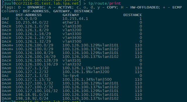
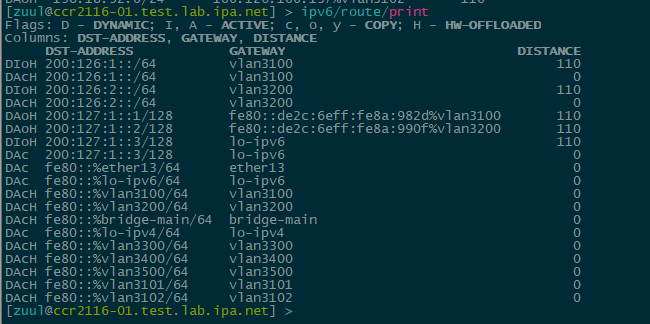
Hardware Offload – Officially, IPv6 HW offload isn’t listed as “done”, but some of the elements are there in the command output and the ‘H’ flag for hardware offload can be seen in the IPv4 and IPv6 routing tables.
Example of IPv4 hw offloaded routes on the CCR2116
Example of IPv6 hw offloaded routes on the CCR2116 – still not officially supported
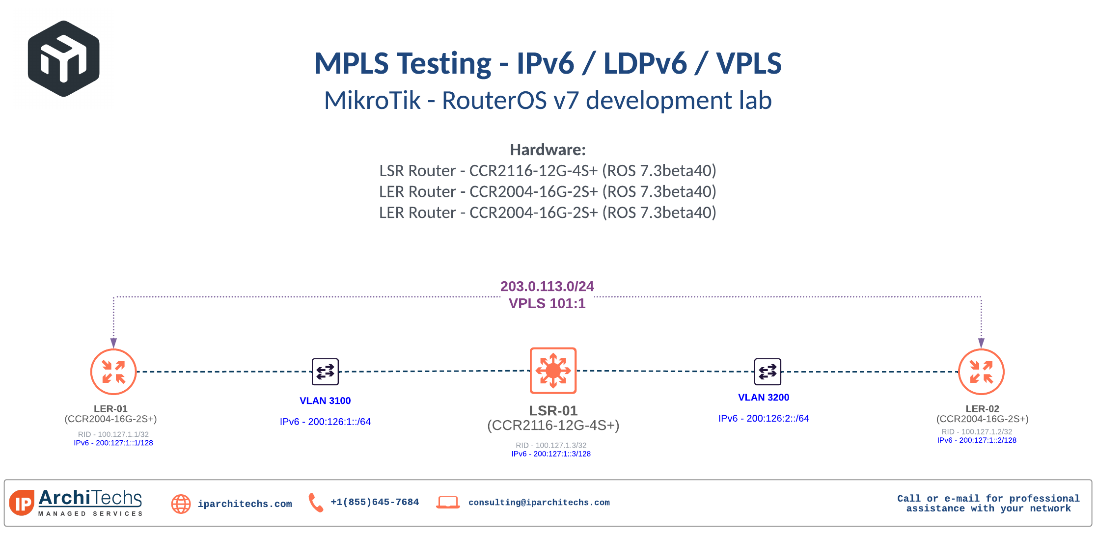
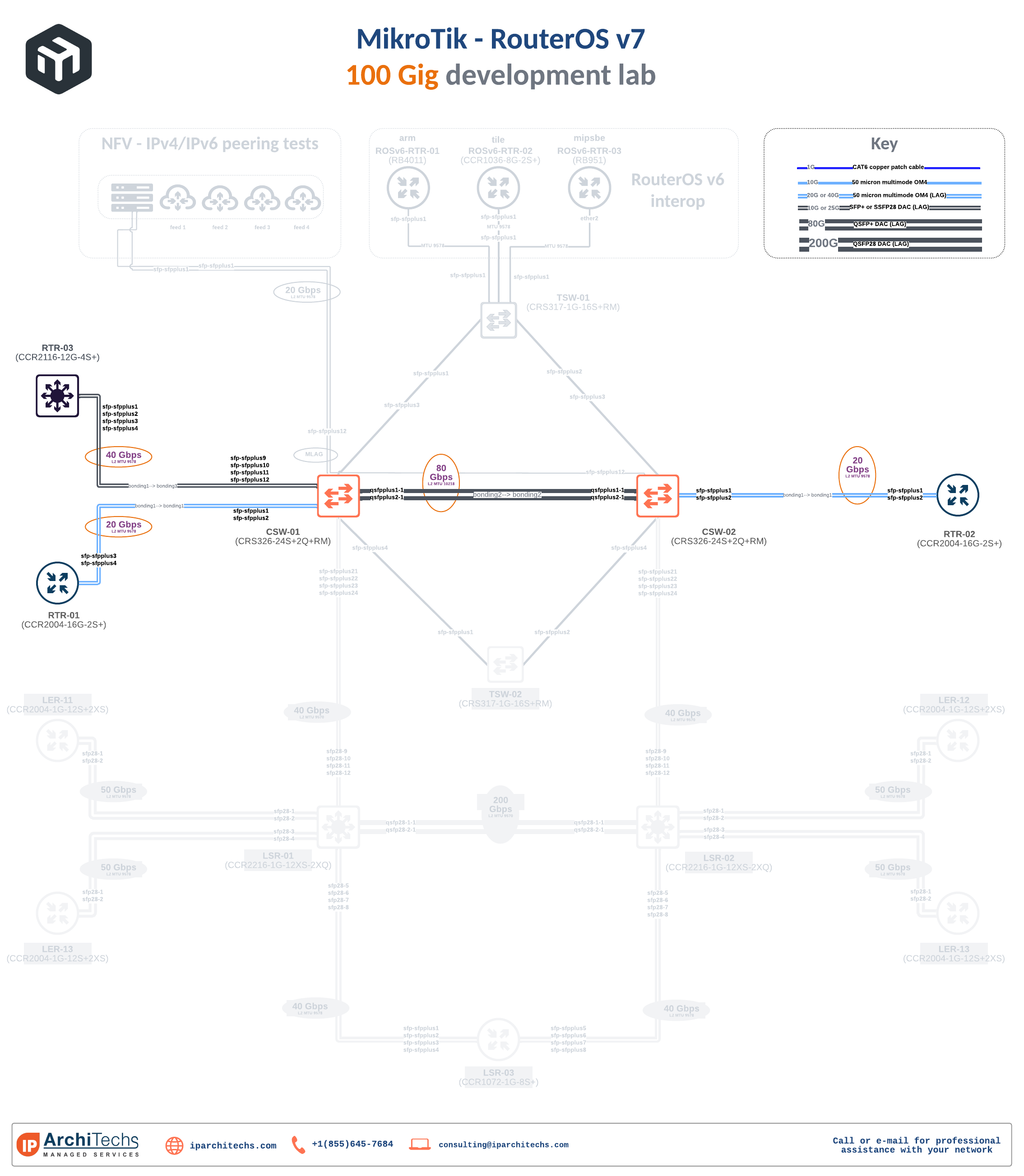
Lab topology
The physical lab consists of a CCR2116 as an LSR and two CCR2004s acting as LERs. They are part of the larger 100G development lab so the relevant part has been highlighted on the physical drawing.
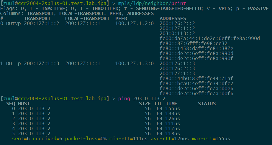
Lab testing
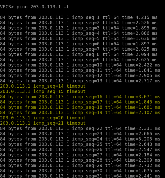
Here is an overview of the config and verification of LDPv6 operation with an IPv4 ping test between the two LER routers.
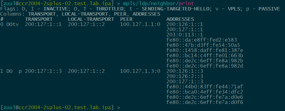
LER-01 (CCR2004-16G-2S+)
verification:
config:
# may/15/2022 12:22:03 by RouterOS 7.3beta40
# model = CCR2004-16G-2S+
/interface bridge
add name=br-vpls-101-ipv6
add name=lo-ipv6
/interface vpls
add disabled=no mac-address=02:DA:E8:D2:E5:83 name=vpls-101-ipv6 peer=200:127:1::2 pw-type=raw-ethernet vpls-id=101:6
/interface bonding
add mode=802.3ad name=bonding1 slaves=sfp-sfpplus1,sfp-sfpplus2 transmit-hash-policy=layer-3-and-4
/interface vlan
add interface=bonding1 name=vlan3100 vlan-id=3100
/routing ospf instance
add disabled=no name=ospf-instance-v3-ipv6 version=3
/routing ospf area
add disabled=no instance=ospf-instance-v3-ipv6 name=ospf-area-0-ipv6
/interface bridge port
add bridge=br-vpls-101-ipv6 interface=vpls-101-ipv6
/ip address
add address=203.0.113.1/24 interface=br-vpls-101-ipv6 network=203.0.113.0
/ipv6 address
add address=200:126:1::1 advertise=no interface=vlan3100
add address=200:127:1::1/128 advertise=no interface=lo-ipv6
add address=203:0:113::1 advertise=no interface=br-vpls-101-ipv6
/mpls interface
add disabled=no input=yes interface=vlan3100 mpls-mtu=1530
add disabled=no input=yes interface=vpls-101-ipv6
/mpls ldp
add afi=ipv6 disabled=no lsr-id=100.127.1.1 transport-addresses=200:127:1::1 vrf=main
/mpls ldp interface
add accept-dynamic-neighbors=yes afi=ipv6 disabled=no interface=vlan3100 transport-addresses=200:127:1::1
/routing ospf interface-template
add area=ospf-area-0-ipv6 disabled=no interfaces=vlan3100 type=ptp
add area=ospf-area-0-ipv6 disabled=no interfaces=lo-ipv6 passive
/system identity
set name=ccr2004-2splus-01.test.lab.ipa
LER-02 (CCR2004-16G-2S+)
verification:
config:
# may/15/2022 14:15:04 by RouterOS 7.3beta40
# model = CCR2004-16G-2S+
/interface bridge
add name=br-vpls-101
add name=lo-ipv6
/interface vpls
add disabled=no mac-address=02:87:6F:98:EE:32 name=vpls-101-ipv6 peer=200:127:1::1 pw-type=raw-ethernet vpls-id=101:6
/interface bonding
add mode=802.3ad name=bonding1 slaves=sfp-sfpplus1,sfp-sfpplus2 transmit-hash-policy=layer-3-and-4
/interface vlan
add interface=bonding1 name=vlan3200 vlan-id=3200
/routing ospf instance
add disabled=no name=ospf-instance-v3-ipv6 version=3
/routing ospf area
add disabled=no instance=ospf-instance-v3-ipv6 name=ospf-area-0-ipv6
/interface bridge port
add bridge=br-vpls-101 interface=vpls-101-ipv6
/ip address
add address=203.0.113.2/24 interface=br-vpls-101 network=203.0.113.0
add address=100.126.1.9/29 interface=vlan3200
/ipv6 address
add address=200:127:1::2/128 advertise=no interface=lo-ipv6
add address=200:126:2::2 advertise=no interface=vlan3200
add address=203:0:113::2 interface=br-vpls-101
/mpls interface
add disabled=no input=yes interface=vlan3200 mpls-mtu=1530
add disabled=no input=yes interface=vpls-101-ipv6
/mpls ldp
add afi=ipv6 disabled=no lsr-id=100.127.1.2 transport-addresses=200:127:1::2
/mpls ldp interface
add afi=ipv6 disabled=no interface=vlan3200 transport-addresses=200:127:1::2
add afi=ip disabled=yes interface=vlan3200 transport-addresses=100.127.1.2
/routing ospf interface-template
add area=ospf-area-0-ipv6 disabled=no interfaces=lo-ipv6 passive
add area=ospf-area-0-ipv6 disabled=no interfaces=vlan3200 type=ptp
/system identity
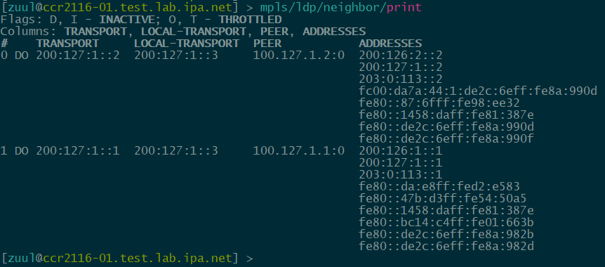
set name=ccr2004-2splus-02.test.lab.ipaLSR-01 (CCR2116-12G-4S+)
verification:
config:
# may/15/2022 11:54:07 by RouterOS 7.3beta40
# model = CCR2116-12G-4S+

/interface bridge
add frame-types=admit-only-vlan-tagged name=bridge-main vlan-filtering=yes
add name=lo-ipv6
/interface ethernet
set [ find default-name=sfp-sfpplus1 ] auto-negotiation=no speed=10Gbps
set [ find default-name=sfp-sfpplus2 ] auto-negotiation=no speed=10Gbps
/interface vlan
add interface=bridge-main name=vlan3100 vlan-id=3100
add interface=bridge-main name=vlan3200 vlan-id=3200
/interface bonding
add mode=802.3ad name=bonding1-40g-crs326-01 slaves=sfp-sfpplus1,sfp-sfpplus2,sfp-sfpplus3,sfp-sfpplus4 transmit-hash-policy=layer-3-and-4
/interface ethernet switch
set 0 l3-hw-offloading=yes
/routing ospf instance
add disabled=no name=ospf-instance-v3-ipv6 version=3
/routing ospf area
add disabled=no instance=ospf-instance-v3-ipv6 name=ospf-area-0-ipv6
/interface bridge port
add bridge=bridge-main interface=bonding1-40g-crs326-01
/interface bridge vlan
add bridge=bridge-main tagged=bonding1-40g-crs326-01,bridge-main vlan-ids=3100
add bridge=bridge-main tagged=bonding1-40g-crs326-01,bridge-main vlan-ids=3200
/ipv6 address
add address=200:126:1::3 advertise=no interface=vlan3100
add address=200:127:1::3/128 advertise=no interface=lo-ipv6
add address=200:126:2::3 advertise=no interface=vlan3200
/mpls interface
add disabled=no input=yes interface=vlan3100 mpls-mtu=1530
add disabled=no input=yes interface=vlan3200 mpls-mtu=1530
/mpls ldp
add afi=ipv6 disabled=no lsr-id=100.127.1.3 transport-addresses=200:127:1::3 vrf=main
/mpls ldp interface
add accept-dynamic-neighbors=yes afi=ipv6 disabled=no interface=vlan3100 transport-addresses=200:127:1::3
add accept-dynamic-neighbors=yes afi=ipv6 disabled=no interface=vlan3200 transport-addresses=200:127:1::3
/routing ospf interface-template
add area=ospf-area-0-ipv6 disabled=no interfaces=vlan3100 type=ptp
add area=ospf-area-0-ipv6 disabled=no interfaces=vlan3200 type=ptp
add area=ospf-area-0-ipv6 disabled=no interfaces=lo-ipv6 passive
/system identity
set name=ccr2116-01.test.lab.ipa.net
“Why use 200::/7 for labbing instead of 2001:db8::/32?”
IPv6 is long overdue for a dedicated GUA labbing space. I’ve been working with Ed Horley (@ehorley) and several others on a dedicated range for labbing that allows for modeling not just within a /32 but beyond a /32
draft-horley-v6ops-lab-02 – Expanding the IPv6 Lab Use Space (ietf.org)